
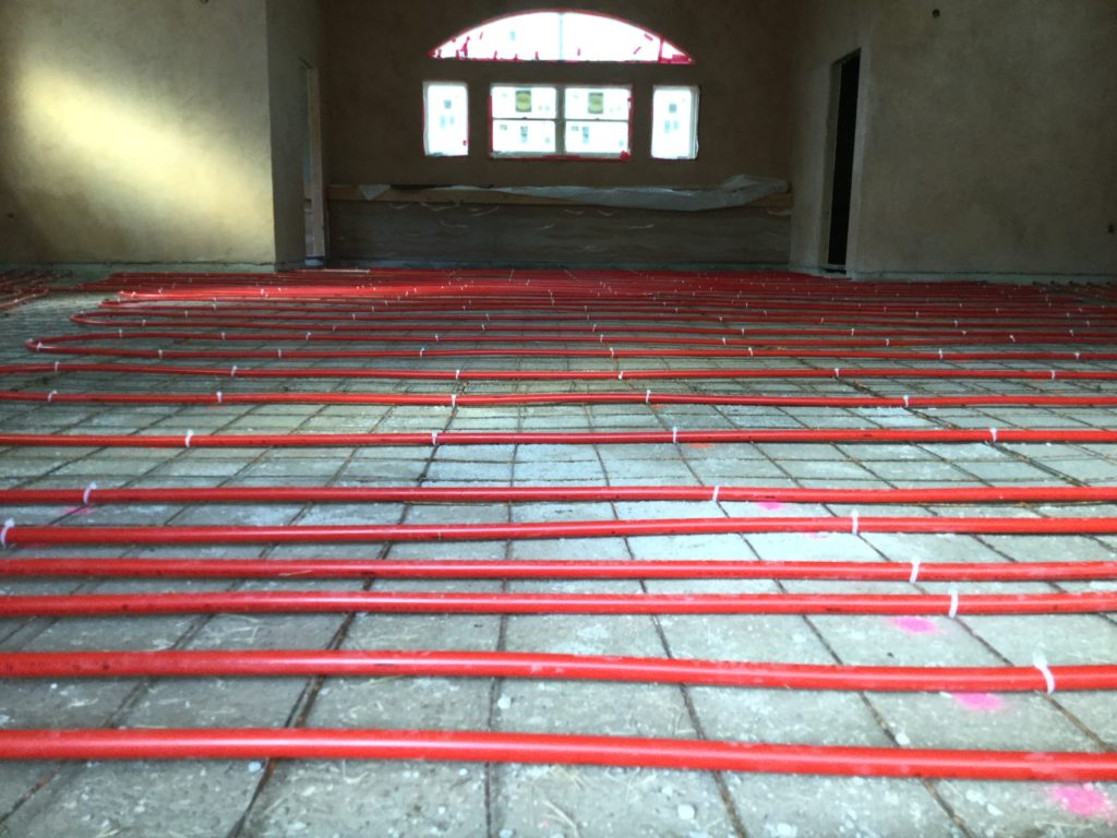
The BBHSP community meeting space is called “Straw Hall” because it has walls and insulation mostly made from rice straw bales, grown by the late, great Rick Green (build leader of Straw Hall). The floor is made from very thick NHL (Natural Hydraulic Lime Plaster, built by plaster master Lin Spier), and includes insulating layering, structural rebar, and a network of Pex pipe for the hydronic radiant floor heating system. We plan to heat the building using geothermal energy (providing hot water to the system’s heat-exchanger), but for now, the systems operates using it’s “back-up” heat source: a tankless propane water heater (AKA “boiler”). This web page is intended to store information about the hydronic in-floor heating system, as we work out the bugs and improve its functionality and efficiency.
A supply manifold and a return manifold divide and circulate the heated working fluid through the floor in four independent zones, which can be adjusted or isolated (turned off), as needed. We are experimenting with trying to improve heating efficiency and effectiveness by running the system without sending heat to the two perimeter zones (#1 and #2, shown on floor plan schematic, below).
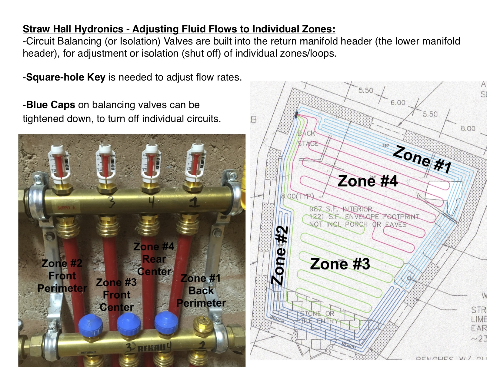
Increasing Effectiveness of Room Heating: Since the floor in Straw Hall (made of Natural Hydraulic Lime) is so thick, the hydronic heating pipes are not heating the floor or the room as well as expected, with standard settings on the boiler, heat exchanger, manifolds, and pumps. We are continuing to experiment with adjusting the water temperature and restricting flows in different zones, to see if we can increase the temperature of the working fluids running through floor pipes, and thus warm up the floor and room faster and with less energy use. Switching to a geothermally-powered electric tankless water heater might help, when we are producing our own power, but for now, we are getting to know how changing the flows and heat-exchanger settings affects the system…
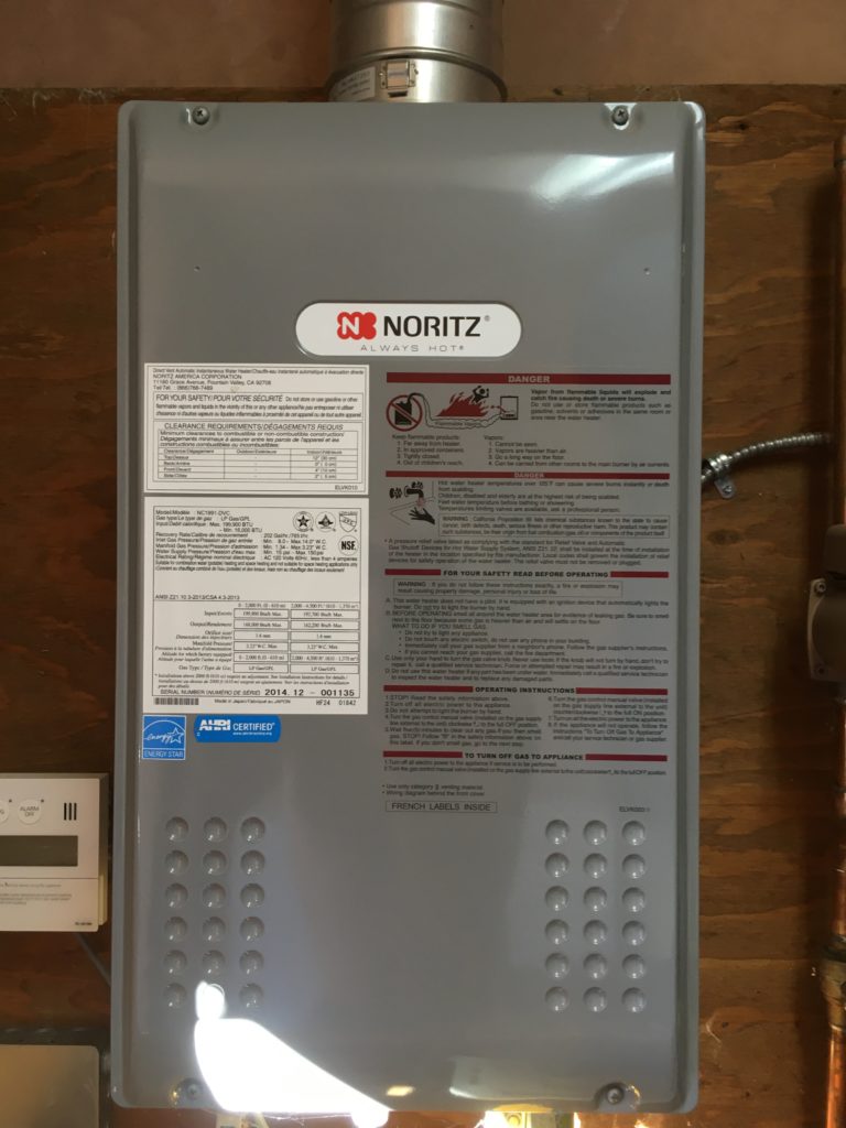
In Straw Hall’s “mechanical room”, the back-up water heater (left) is set up as a closed-loop system, providing hot water to the shell-and-tube heat exchanger (which is the gray cylinder in the center of the picture below). A second closed-loop system has special working fluid, which is heated by circulating through the heat exchanger and pumped through the hydronic floor pipes, to warm up the large thermal mass that is the lime floor…
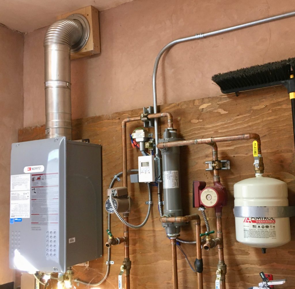
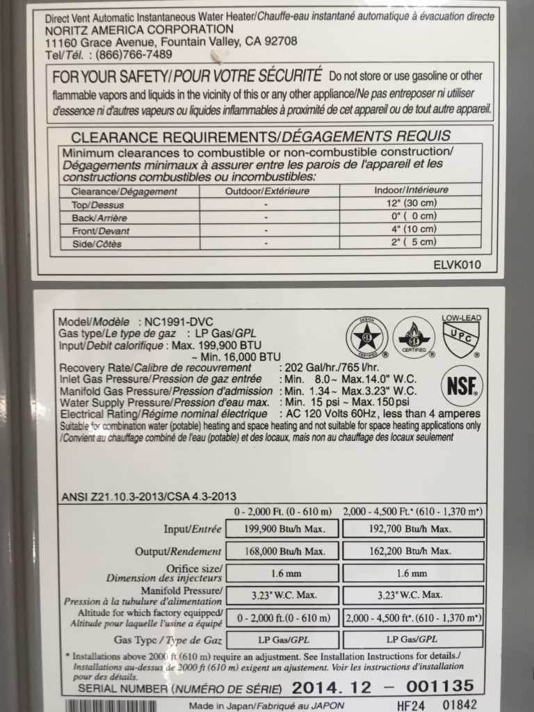
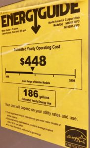
The back-up water heater boiler unit is a propane Noritz Always Hot Model NC1991-DVC.
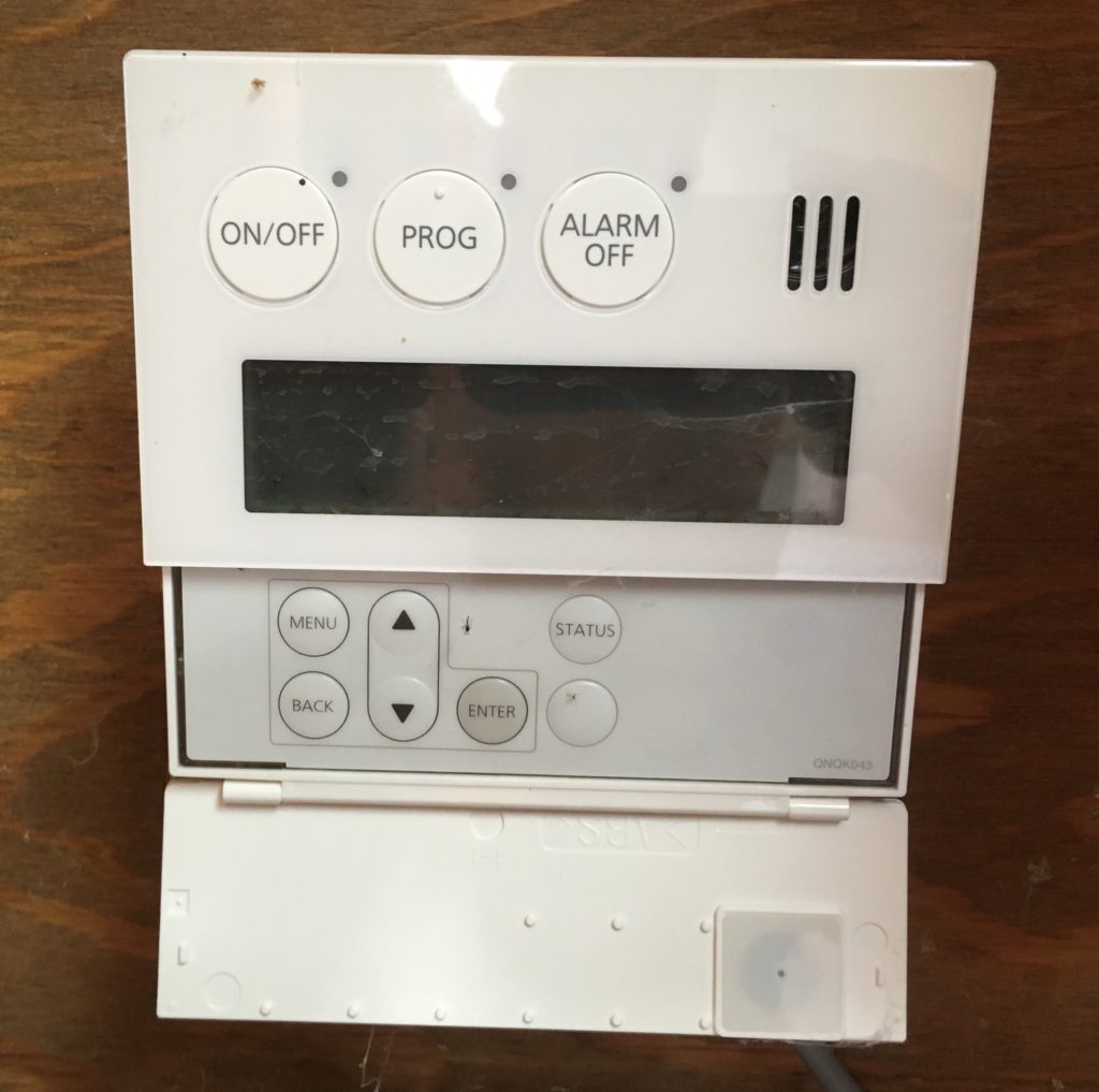
The remote controller (below) controls the tankless water heater, including the water temperature and when it can turn on and off.
What is the maximum setting?
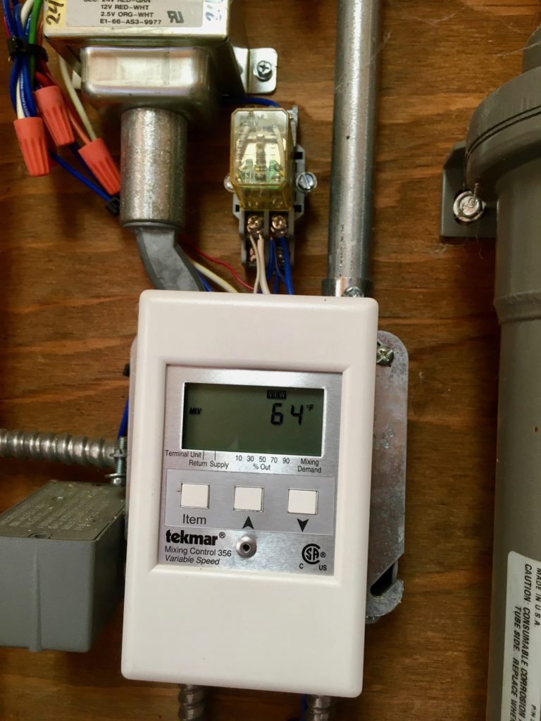
This variable speed mixing controller (below), monitors the heated supply fluid as it exits the heat exchanger, and apparently controls the heat exchanger flow rates by varying the pump flows of both the water heater loop and the hydronic circulation loops. The mixing controller helps to maximize the heating effectiveness and efficiency in that way. We need to learn more about what the optimal settings are for the unique Straw Hall hydronic system.
When we have the in-process GPP (Geothermal Power Plant) up and running, we pan to replace the existing propane-powered boiler with an electric tankless water heater, since we will have an abundance of “green”electricity, generated on site from geothermal energy (and some solar panels too).
(Maintenance costs will still be a factor, when needed).
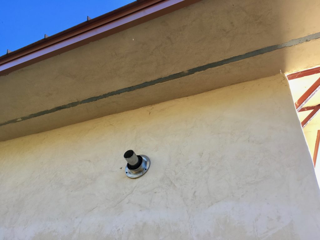
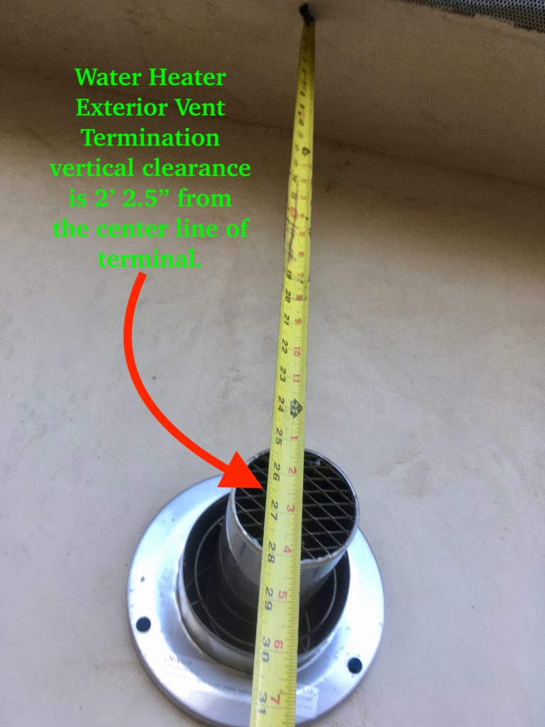
Exterior Vent Pipe Clearance:
Straw Hall (including its current heating system) has passed the Shasta County Building Division’s final inspection, but before it was give final approval, a building inspector required us to prove that the venting termination had adequate clearance… “WH (Water Heater) exhaust within 2 feet of eave vents. Consult Install Guide, as needed” Making sure the vent pipe had indeed been installed to meet the building codes took some time and research, but the installation eventually proved to be perfect.
The exterior vent pipe termination outlet from the boiler has over two feet clearance (it’s 2′ 2.5″) from the soffit venting above the termination. The boiler’s manual and relevant building codes call for at least two feet of clearance, so the installation was done correctly.
STAY TUNED: This post will be updated, as we continue to learn more and improve the system.